Saturday, December 24, 2005

in praise of older machines

I believe that just because something is older, it isn't necessarily useless or bad. Sometimes old is good and even better than new. Particularly these days when new has come to mean cheaply made, unrepairable or throw-away.

There are many older machines that with a bit of care, repair or restoration can be made to function as well as when they were new, or even better in some cases than the "latest and greatest".

In many cases, knowing what you have, what you need and how to use it are more important than having the very latest. Keeping older stuff going longer not only can cost less than getting new, but it also keeps it out of the landfill. In many cases, older machines discarded by others can be had for free or next to nothing. I am often amazed by what people throw away.

Take my snowblower above for example. I purchased someone else's trade-in for $250 at a local shop. This 1960 something "Snow Bird" is probably one of the first such snow throwers available. It has the original Briggs and Stratton L-head 6 hp engine and most of its original parts. There is only one speed and no safety devices at all. We call this little tank "Annie" (after Canadian singer Ann Murray's big hit "Snow Bird"). This is Annie's third year helping us keep the driveway clear of snow and as I learn more about her and make various repairs and renovations, she just keeps getting better and better.

Post script - Annie died and was replaced with a much newer and very much more functional machine. Sometimes one can go so far back to be noticably less functional. Anne was noble but only had one speed. It was, after all, much harder in the old days!

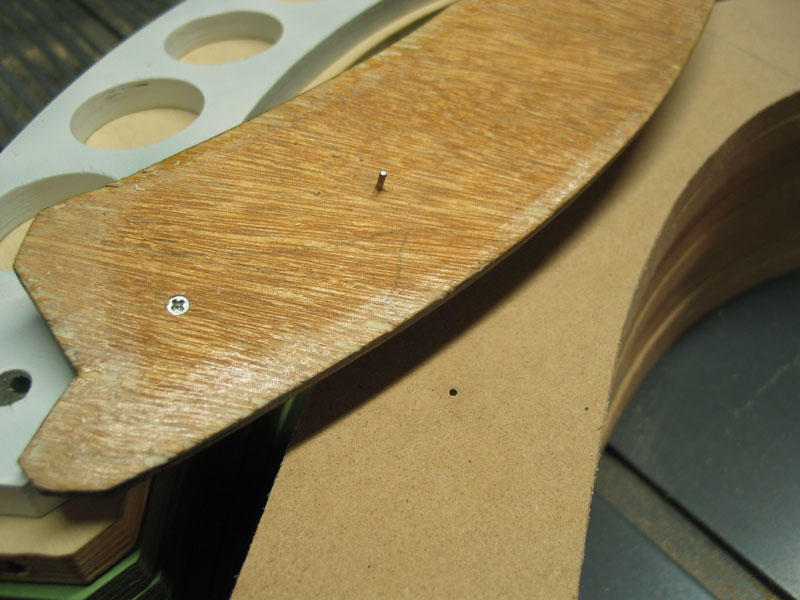
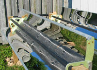
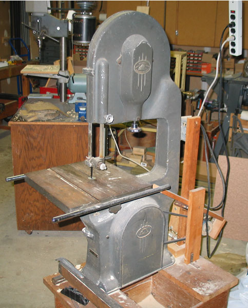
One of my other favorite older machines is a "Beaver" 14 inch bandsaw purchased from a local cabinet shop that was downsizing for $200 about 20 years ago. I installed new bearings and guides then and once in a while, I clean the sawdust out of the original electric motor. This fine machine has done many projects for me including the production of the reflector ribs for the solar parabolic heater. Produced in Guelph not far from here, probably in the 50's, before Beaver was consumed by Rockwell who then knocked down the factory and moved production to the orient. With a bit of care, this sturdy machine will probably still be cutting wood many years from now.

The newer bandsaws look nicer but are not, in my opinion, anywhere nearly as solidly built as my old Beaver. Certainly they don't cut wood any faster or cleaner.

Of the three cars in our family, two have over 280,000 km and the other has just passed 160,000. They look good and run well and get us where we need to go. None of them are SUVs. Changing the engine oil very regularly and generously replacing or fixing the parts that break help to keep the three machines going strong. For what I cannot do myself, I have a good mechanic I can trust. Good sources on the web for information about these vehicles are generally NOT the manufacturer's websites, but third party sites set up and maintained by like-minded owners. For the VW, I particularly like www.vwvortex.com which contains fabulous do-it-yourself information specific to that car.

Sure, they will "wear out" eventually, and rust from the road salt used in our climate eats the metal and can't be stopped but I am determined to keep them running reliably as long as I am able to do so.

I feel the same way about my computing machines. One of my current projects is a matched set of three identical 200MHz Pentium computers running Windows 2000 sp4. The parts came as trade-ins from a local college that was upgrading machines I built for them only six years ago. New inexpensive cabinets, power supplies, fans and hard drives were added and new clean installations of Windows make these machines run like new at very low cost. Having a spare computer or a matched set of two or three can be extremely useful for experimenting with software or hardware before adding it to my "production" systems. More about that project later.

I feel that many people buy new computers because their older machines are "too slow". For most uses, we do not need the processing power that is currently sold and the reality is that our machines are often bogged down with adware, viruses and the debris of programs that did not uninstall properly. It is absolutely amazing the new lease on life that can be had by simply cleaning the drive and reloading Windows onto an older machine.

It is also important to open the case once a year or so and clean the dust out of the fans and check for fans that have stopped working. I once had a customer who brought back her one year old machine complaining of a noise it had developed. I found that the cooling fan on the processor was completely clogged with pet hair and it was the fan turning against the mat of hair that was making the noise! It was easy for me to clean out the hair and restore cooling to the machine. The normal environment of many computers (near the floor) makes them susceptible to collecting dust and getting clogged cooling which can lead to intermittent problems and failure. You don't need to have pets for this to happen.

For a machine that is to be connected to the web, I religiously add anti-virus program like Norton Internet Security or McAfee and keep them updated. The price for me is that the anti-virus software takes more space on the hard drive than Windows and consumes a fair amount of the computer's power just looking out for the bad stuff. This is an incredible waste but an unfortunate sign of the times. For this reason, I isolate my production machines from the web and do not use anti-virus software on them. They are much faster as a result.

I am under-impressed by the "improvements" in the latest Intel product line. Intel has rediscovered the importance of keeping electronic machines cool and the desirability of using less power, as if this was news. Just when we get the bugs out and figure out how to make a reliable system, Intel changes the processor pin-out, the chip set, the cooling and the power systems so that interchangeability is difficult or impossible. If it breaks, you are supposed to throw it out.

I feel that one of the finest mainboards ever made was the ASUS P4C800E Deluxe. It had a production run of about a year and has been "obsolete" now for about a year. Others must feel the same way since these sell on ebay for about the same cost as when it was new. Having installed about 40 of these, I have found that these make a very stable and very fast computing machine at a reasonable cost. These boards will form the basis of my next matched set.

Most recently, I have been adding to my electronic test equipment lab some of the wonderful equipment made in the 60s and 70s by Tektronix, Hewlett Packard and Fluke. These are acquired on ebay or at swap meets or from the local re-cycling center and restored and repaired and recalibrated as they require to working condition.

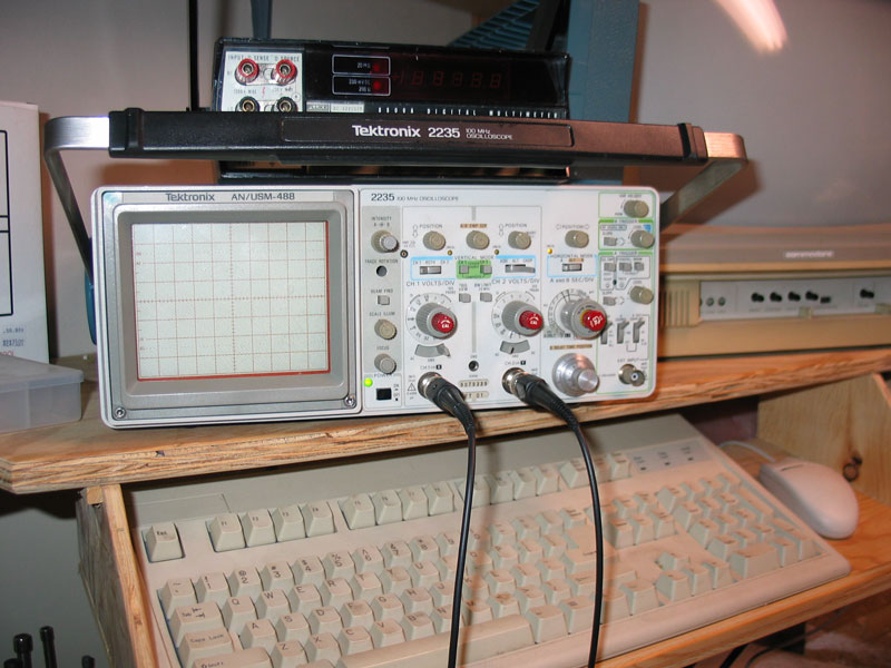
My Tek 2235 scope was used originally by the US Air Force in Texas and was bought on ebay for $150. It works perfectly and is almost as new. It is a thing of beauty to me and 30 years ago probably cost thousands of dollars. I was able to get operating and service manuals easily at low cost in case it ever breaks, or I can probably just buy another one at low cost. These older test machines measure volts amps frequency and waveforms as well as the current equipment, at least in the ranges that I work today. Repair information and users groups exist on the web for this fine, well known equipment.

My digital camera is a Canon G3, bought from a customer at low cost when he got his new G6. Like new, it is way more than I need for my work. My video camera is an original Canon Optura DV, out of production about seven years ago and working beautifully today with a bit of care.

In case I sound like a technological luddite, this is not the case. For most of the last 40 years, I have tried to stay near the forefront of "high technology", often being one of the first to have the newest. Looking back, I see that this has cost me a lot of money and resources.

With my teenage part time earnings in the early sixties, I bought one of the first germanium transistors, the Raytheon CK768. With it I built a speaker amplifier for the crystal radio I had built the previous year. I learned how to program on one of the first IBM 360 machines at the University of Toronto in the late 60's using punch cards. Like a few hundred others I bought the kit and built the first available personal computer: the MITS Altair in 1975 and in fact met Bill Gates of Micro Soft (as he called it then) at the first (and I think only) World Altair Users Conference at MITS in Albuquerque. My business through the 90's involved editing video on computers which was technologically challenging at the time.

With the deluge of inexpensive goods from China and India, I see that we have given away our manufacturing capability in North America. Worse, we have acquired the mentality that our older equipment is no longer useful to us. We no longer teach electronics in high school. The newer stuff isn't really repairable since it isn't designed to be repaired, it is designed to be consumed and thrown away. Service information and parts are not available. People who know how to work on the newer stuff are not common. The powerful global corporate marketing machines force feed us the new features which we can't (or mustn't) live without. The old stuff goes out with the rest of the trash. In many cases it is difficult, impossible, or uneconomic to break down to recycle effectively or safely.

This is a trap for us.

The economies of the east grow as we "consume" their goods bought at artificially low prices, but the prices will rise much higher. Lead by their "consumption" of oil and raw materials, we are already suffering increased costs of almost all goods that must be transported. Soon the cost of the manufactured machines will rise even higher and our economy will falter as we are less able to "consume". We will be forced, by economics, to keep our older stuff running longer. We should get ready for that. Besides, I very much resent being called a "Consumer" and we are already having trouble getting rid of our garbage (old stuff).

This will only get worse.

Thursday, October 06, 2005

collector tubes

Collector tubes are the "business end" of this DIY tracking solar concentrator project. The collector tube at the focus of each reflector absorbs and conducts the sun's heat to the water which travels through it.

Shown here are four copper collectors and one glass/copper collector that I made to test as a concentrated UV sterilizer.

The black coating on the copper is ordinary matte black high temperature spray paint, like Tremclad or the local house brand. I found that the most efficient way to coat the tubes was to line them up like this between the supports and blast them with paint from a spray can. In this way, I could aim the spray toward one tube, travel down that tube to the end and then move back along the next tube trying to get an even light coat with no drips. The overspray from one tube would then fall on the tubes behind it. When that pass was dry to the touch, I'd rotate the tubes about 60 degrees and paint another pass. With a bit of practice, I could coat the tubes with a uniform looking two coats of black in about six passes.

I'd considered and tested many different types of tubing. The tubes needed to conduct heat well, be strong and resistent to sagging, not burn up in the case of a failure, and must be easily joinable to a conventional PVC plumbed system.

The collector tubes must span 8-1/2 feet between the supports. As well as it's own weight, each tube supports it's reflector and the weight of the water within it. With the 1-1/2 inch diameter size I'm using, that's about 10 pounds of water that is contained in each tube over its length.

I'd built a temporary test setup with two sawhorses spaced parallel 8-1/2 feet apart and measured the sag of various tubing. This involved placing each tube across the top of the sawhorses and putting a 90 degree elbow on both ends, facing up, so that I could fill each sample tube with water. To keep them from rolling around, I placed each tube in a metal V block on the top of each sawhorse. A plumb bob was hung from the center of the tube and the distance from the tip of the plumb bob to the ground was measured with a small ruler to an accurancy of about 1/2 mm.

It became apparent pretty quickly that any plastic tube had way too much sag over this distance and with this weight. If used as a collector the plastic pipe would sag out of focus. The copper tube sagged only about a millimeter, which was surprisingly good and almost less than I could measure. Copper tube also felt very "stiff" when I pressed down at the center while the plastic tube "gave" quite a bit.

The plastic tubes (both ABS and PVC) sagged as much as 10-15 millimeters. Worse than that was their "memory" and their lack of inherent straightness particularly if your home center keeps their tube inventory in vertical racks. The PVC tube was the worst in this regard and even selecting carefully, I found it hard to buy tubes that looked at all straight.

For this solar heater project, I've settled on the use of copper tubing for the collectors but glass is still being looked at for a sterilizer variation.

The copper tubing of this size at your typical home center or hardware store is DWV type (or Drain Waste Vent). This is what I started with. There are other grades of copper tube available at plumbing supply houses that might be an even better choice.

In this picture (click to enlarge) you can see the difference between DWV tubing (at the top) and M-type copper (on the left) and L-type copper (on the right). DWV is intended for low pressure and temperature. M-type is sold for regular waterline and L-type is for high temperature. You can see the significant difference in the wall thicknesses here. I'm not sure yet if the composition of the copper alloy is different between the three types but I've heard it might be. When you carry them, you can feel that the DWV is "lightweight" compared to the other two.

I have used a combination of the three types in the current assembly of the concentrator and will make further comments as I progress. Any of the three types of copper could be used. As you might expect, both M and L types are significantly more expensive that DWV (about twice) although there isn't as great a difference in cost between them.

Sunday, October 02, 2005

assembly notes

Winter is coming here in southern Ontario. The leaves are changing colour and soon will start to fall from the trees. Our swimming pool must be closed up for the winter. The tracking parabolic solar heater project that has been under construction here this summer didn't add any BTUs to the pool during September, although it did give us heat earlier.

In the picture (which enlarges if you click it) you can see the ends of the copper collector pipes which require connecting together. On the ground behind are two unmounted reflectors which are waiting for their copper collector pipes.

My goal in this project is to use readily available materials, such as would be available at the typical home center "box stores" that seem to be everywhere now. I was mulling over the type of copper collector to use.

I've decided to go with the L-type copper pipe. In my case, I'm using standard 1-1/2 inch size, (North American Schedule 40 size plumbing pipe). You will probably have to visit a plumbing supply since the box stores only seem to carry the DWV (drain waste vent) type of copper. L-type is approved for hot water and is about twice the wall thickness and price, but probably worth it in durability. If you want to use a different size, you can by changing only the size of the drilled holes in the support plates and the size of the clamps that fix each pipe to the frame.

The last of the six reflectors is about to be assembled. You'll notice that I've added large holes to the ribs to cut down on weight. The ribs aren't very heavy but the holes help improve the balance axially around the collector pipe. Better balance means the motor doesn't have to work as hard to move the reflector to follow the sun. The balance currently is such that the reflectors naturally pivot to the horizontal position seen in the first picture in the absence of the drive motor.

In the parts laid out on the floor, you'll see the seven ribs that make up a single eight foot collector unit, the two side rails that join them together and the screws that that secure the ribs to the rails (four sets times seven ribs). I didn't get the large holes into all of the ribs before painting.

Here I've snapped in place the reflector sheet, but haven't yet tightened the screws. It helps a lot to have a relatively flat surface to work on and it would be great if I had an eight foot long table available since it takes a while to line eveything up.

Once the reflector material is held within the rails, it forms a curved shape which when tightened down with the screws presses quite nicely against the parabollic shape of the inside curve of the ribs.

The screws are each getting a dab of anti-seize compound appied to the threads before assembly. The screws are stainless steel but the mating nuts are plain steel and rust quite rapidly once outside.

Wednesday, August 31, 2005

making more ribs

This is a great rainy day project: making ribs for your solar collectors. You'll need quite a few of them once you've decided to scale-up and make a larger working system. Each eight foot collector needs seven of these. Six collectors need 42 and so on. A general rule of thumb I heard for heating a swimming pool was to have one third to one half of the surface area of the pool in the collector, so you can start doing some math on your application.

The ribs shown here are at various stages of completion. The green ones on the bottom have received the two-part marine primer sealer coat and are ready for the top coat. As these ribs are made from wood they need to be sealed from the weather.

All of the ones shown above are one half inch (also sold as 13mm) "baltic plywood" which is a terrific material to use where relative precision and strength are required in a panel material.

The white one with the extra large holes is experimental and has the final resin topcoat in white. The large holes give it more of a space age look but their actual function is to lighten the rib on the bottom of the collector panel to improve balance at the collector tube/pivot. I felt that I could remove material using the large sawtooth forstner bits that I bought to make the through holes for the collector tubes. The baltic ply material is very stiff and punching the holes does not seem to adversely affect the strength of the rib in the direction we need it to be strong (mostly lengthwise).

Making the large holes with a forster bit didn't work out very well with the plywood ribs, since without using clamps for each individual hole, the plywood tended to tear out at the back. Aside from the cosmetics, this created a problem for weathersealing and much patching and sanding was necessary to get a clear looking sample. This was solved but took more work. Each hole (there are nine in each rib) requires individually repositioning and clamping the rib to the drill press table, using two clamps, one on each side of the hole to keep the rib on the table firmly as the forstner bit comes through the rib.

I'm trying some ribs made from from MDF (medium density fibreboard) material which is also a fairly common furniture making material available at many home centers. We'll see shortly how the MDF comes out. You could also make the ribs from a plastic sheet material although I haven't tried that. I suspect that a plastic sheet of acrylic, lexan or UHMW would not have the stiffness of wood, although using plastic would eliminate the coating steps which are significant.

When selecting material for the ribs, the minimum thickness is the half-inch material used here but it could be thicker unless the weight became very much greater. Given that the design needs bolts sunk into the ends of the material with some precision lead me to the half inch material I am using.

Here's my first batch of MDF ribs with the first jig on top of the stack. The funny handles are actually off-cuts from the band sawing rough cut operation but ended up being quite functional as hand grips to guide the jig and rib over the router table for the edge routing operation.

I can get ten ribs out of a 2x4 foot piece of material, since they are about 23 inches at the widest point.

The technique I use is suited to a small shop for hand production of a hundred or so ribs (a dozen collectors takes 84 ribs). I've thought that they also could be molded out of recycled plastic, but here I am individually making each one by cutting it out of a sheet and then routing the edge. The ribs above are sitting on my small routing table (the cheap kind with the hand router hanging upside down underneath).

Here's another detail of the top of the jig on top of an MDF rib which has been edge routed using the jig. The 10cm refers to the focal length of the parabola made from this jig. This means that the copper tube is centered 10cm from the bottom of the reflector to achieve design focus.

The small metal strap is cut from a roll of galvanized strapping and used to brace the glued and screwed attachment of the off-cut handles to the jig (two more small screws come up thru the bootom).

The MDF rib has only a small burr which is removed by a light hand sanding. The edge is very nice with no breakouts. Of course, the inside edge is very much more important than the outside edge, since it is the inside that forms the basis for the curviture of the parabola. The metal rails hold the reflector sheet onto this edge. I estimate that with my jig and technique, I am achieving an accuracy on the parabolic curve of about a millimeter from the ideal.

This is the bottom view of one end of the first jig. There are two of these short pins on the jig, one at each end. The pins are actually small steel nails of about 1mm diameter. They are epoxied into the jig and cut off so that about 3mm protrudes thru the bottom.

The two mating holes drilled into each ribs are actually the first step in making the rib, since they guide the loaction of all subsequent machining operations. The pins lock the jig to the rib.

The jig is handmade from 1/4 inch scrap and patched and filled, especially along the edge, to guide the ball bearing cutter mounted at the top of the router bit. The jig could have been made out of any type of material including metals like aluminum.

There is a second jig for the ribs, and it is shown here on top of the stack, held in place to the top rib with two 1mm dia nails which fall into the locating holes marked with the first jig.

I'd originally thought to just have one jig, with the position of various holes marked in it, but the need for strong handles on the routing jig meant that some of the holes would be underneath the handles. So I simply used the first jig to make a copy out of another piece of 1/4 inch thick scrap and marked and drilled the location of the holes that would be necessary.

Using a small center punch, the second jig is used to transfer the location of all the holes to the top of each rib. Depending upon what type of rib it is (there are several variations), some holes are drilled, while others are omited, but all the holes are marked in this manner in each rib. These small dimples in the surface guide a drill bit's starting location in the subsequent operations.

This is the top of the second jig, showing the highly accurate method of locating the jig using small nails. Remember that the accuracy I'm aiming for here is about a millimeter and this seems to be adequate for the purpose, using the simplest tools and equipment for the job.

The material here is 1/4 masonite which makes a good jig material. The jigs should last a long time, provided that you don't damage them. It's a good idea to make a spare or two, just in case.

Also you can see again the fine slivers of material on the top edge of the MDF. This is nothing to be concerned about. The edge is actually very smooth and precisely follows the jig. The fine sliver comes off easily with a light hand sanding.

It's not a solar day today since it's raining. Time for me to go and make some more ribs.

Thursday, August 25, 2005

frame construction


The hard work of building a solid frame for up to 12 reflectors is pretty much finished now. I'm watching the concrete footings dry in the cool early morning.

I took apart the original structure to build this in it's place. In the last couple of weeks, the night-time temperature has definitely had a chill and without even the two reflector system for heat, the pool temperature has fallen to about 72F. The days are hot, but no-one wants to swim. We haven't used the propane heater at all this year and aren't going to start it up now.

I've built this structure to hold the next set of collectors, up to twelve in all.

It's made of pressure treated 4x4's. They are held together by galvanized metal joining plates from the hardware store using deck screws. The vertical ones are four feet in length and are sunk about 18 inches into concrete in ten inch sonotubes.

The structure forms a couple of straight parallel beams, about four feet off the ground and eight foot six inches apart. The reflectors will hang from this structure, with the pipe spanning the gap. The pipes will be installed with their reflectors at two foot intervals between the beams.

In spite of some difficulties like twisted beams and rocky ground, the final top beams ended up very straight, probably much straighter than they need to be, about a quarter inch over the each 24 foot length and parallel by the same tolerance. Hopefully they will be still be straight and parallel after the frost heaves the ground a few winters!

As I push against the these beams, set in concrete to test their satisfying stiffness I wonder if I haven't gone a bit overboard with the structure? After all, this frame will support the weight of several hundred pounds of water and copper pipe and must also withstand whatever wind load that nature will provide. So I'm happy that this support is adequate for my solar heater.

While it involved ripping out the previous prototype, I've gone to this type of structure primarily for simplicity. The previous method, that of passing the collector pipes through a holes in beams, was far too complicated to line up correctly and required one set of posts for each collector. With the new parallel beams, the collectors will just "drop into" the frame and be screwed into place with two pipe clamps, one at each end, into the beam. Couldn't be stronger or simpler, could it?

It's close to the ground to make it easy to work on and to cut down the wind load. I plan to surround it with a fence of the same, four foot height, to reduce the wind load.

Also considered, but rejected this time around, was to drop the southern facing beam about a foot or so to better match the sun's track, but I decided to make them parallel in the horizontal plane for simplicity of the control mechanism and because a thrust bearing would be required at the lower end. Perhaps I'll tackle that on another iteration.

It's important to store the 4x4 beams for a while in a dry place, like the garage for a month. Turn them over once in a while and check for any beginning warpage. I've been doing a few outdoor structures this year and have of pile of wood in storage in this manner to weed out the troublesome ones that are going to warp. There is no guarantee with wood however and the placement and final orientation to the sun may determine whether a beam is going to warp or not. Incidentally, the warped ones (there were several) were chop sawed into the four foot lengths for the vertical supports. The fact that they were twisted slightly over their length down into a concrete footing didn't make a lot of difference and used up the troublesome timbers.

One final word on the mirrors. We dropped one of the collector pipes into a reflector when removing it and the mirror did break, although not into thousands of little pieces like glass. Here's what it looks like.

Fortunately, the reflector material is easy to change if necessary and with the plastic mirror the cost of each is about $40.

Monday, August 01, 2005

parabolic reflectors

The DIY parabolic heater uses thin sheets of reflective material gripped along the two long edges in a ribbed frame shaped like a parabola. This forms a rigid parabolic trough when the frame is tightened to snug the sheet into the frame.

The reflector ends up looking like a shiny inside-out canoe. The parabola is shaped to bounce sunlight onto the pipe which is at it's focus. The pipe also serves as the support for the collector and it's the pivot to allow the heater to follow the sun. The collector pipe doesn't move.

Each frame holds one two foot by eight foot sheet. What type of sheet you use depends upon your budget and what is available in your local area. As the reflector sheet is one of the main cost elements of the heater, I did a fair bit of research on what was locally available and you will too. In the large metropolitan area outside Toronto, I found that there were plenty of choices and I managed to test a few.

The most expensive, but most impressive, at about $8-12/sq.ft. (German made MIRO IV) is an optically clear anodized aluminum electro-polished material sold by a local distributor in Brampton for use in light fixtures. Curiously, the distributor does not recommend exposure to the elements. We'll see. I've had a sample outside for almost a year now and it seems to be holding out very nicely.

The cost of building only two heaters with MIRO IV is estimated to be about $300 but the cost comes down slightly with larger quantities. MIRO IV is like a metal mirror and the reflection of light in ideal conditions is over 95%. It is an almost perfect mirror that can be bent. One nice feature of MIRO IV is that it is fairly stiff material at about 0.20 inches thickness, so it sits firmly in the frame and is quite strong. My only concern, other than the cost, is the long-term effects of having the aluminum in contact with the galvanized edge of the frame. This will undoubtedly lead to galvanic corrosion at that interface.

In this picture, the reflection at the top is from the MIRO IV material, at the bottom is the clear aluminum sheet roofing material (described below). The one in the middle is another product called Anolux which is only slightly less expensive than MIRO IV.

I also tried galvanized steel sheet which I found at the local building center, conveniently cut into 2x8 sheets at only $15 bucks a sheet (about $0.50/sq.ft.!) and learned about the significance of Herscel's infrared experiment in 1800. The galvanized steel showed me that even with a relatively "dull" material that the infrared portion of the sun's energy contained a lot of heat (about half). In a side-by-side comparison, the galvanized sheet contributed about half of the heat energy as did the Anomet material, making it's cost per BTU a lot lower.

The galvanized sheet when new is quite shiny, in a blotchy sort of way. This is the zinc coating that sacrificially corrodes and thereby protects the steel underneath from rusting. You've probably noticed how galvanized metal turns dull and flakes of white oxide form on its surface. Eventually the zinc disappears and the steel rusts. This process depends on the weather and the amount of acid and salt in the air. Just how long reflectors made of galvanized material would be tolerable I don't know. But they do reflect infrared (the visible part of the spectrum is scattered or absorbed). It's interesting that the galvanized material gets quite warm to the touch which wouldn't be the case if it was doing it's job and reflecting all the sunlight onto the collector tube.

One more thing about the galvanized: it is a low cost way to build a prototype that can be later replaced with something better. To replace the sheet in a frame only takes about 10 minutes, so it is easy to upgrade or replace a corroded sheet.

I tried an aluminum sheet product that is sold to the roofing trade for flashing (for about $1-2sq.ft). It is available in standard widths, usually on a roll, at the home centers and comes in various colors including "clear" or natural aluminum. This material in the clear aluminum form produces heating results similar to the galvanized and is a lot thinner, only about 10 thou thick. This makes it slightly harder to handle as it is quite "flippy". You can distort a sheet by mishandling it and produce a crease in the material that ruins the optical properties in that region of the sheet. Also, as the sheet is not anodized like the Anomet and it will degrade more quickly over time like the galvanized sheet. I decided not to use the aluminum further. Although it may make a great prototype material and seems to be readily available in precise and clean 24 inch widths up to 200 feet long.

Any roll material would need to be cut into 8 foot lengths to fit the collector frame. I found it difficult to get clean cuts using tin snips on any of the sheet metal products and I tried to buy them where ever possible in the 2x8 final form.

The winner so far is an acrylic clear plastic mirror material that I only installed about two weeks ago at a cost of about $1.50/sq.ft. This is a 1/16 inch thick version of the plastic mirror used architecturally in public places where they don't want breakable glass mirrors. A local plastics distributor had in stock the 1/4 inch thick acrylic mirror material which I didn't think would bend into the frame easily. They special ordered the 1/16 inch thick version for me.

The acrylic mirror goes into the frames beautifully, although even at 1/16 of an inch it is by far the thickest reflector I've tried. The quality of the reflection and focus is as good, if not better than the Anomet.

The acrylic mirror needs care in handling because it can be broken if bent too far. It becomes strong in the frame but getting it there needs two people.

The long term durability of the plastic is uncertain at this point, but it gives good reflection per dollar and it doesn't get hot in the sun showing that it is doing its job.

I'm not sure about galvanic corrosion where the acrylic mirror (which is probably sputtered aluminum) touches the galvanized frame. We will see with time.

Thanks for your interest.
George Plhak

Sunday, July 31, 2005

DIY tracking solar concentrator project

This is my "Do It Yourself" project for a high-performance but low-cost modular home-built solar water heater that is largely made with common tools and building supplies.

It is also way cooler to have one of these than the traditional flat plate design that most people think about when they consider making a solar heater.

Here is another prototype (my third) of the solar tracking heater just before I take it apart somewhat to make some modifications.

This one has run well throughout the month of July here just outside of Toronto, Canada and certainly has warmed our swimming pool several degrees each day. Without water in the system, the central copper collector tubes can reach 270 degrees F although when it is operating with pool water flowing through it (about 60 gallons per minute), the heat rise is hard to measure, less than a degree F. The pipes are cold to the touch although the wood frame heats up a bit where the concentrated sunlight spills off the ends.

The motor drive has performed well and moves the collectors smoothly. The new plastic reflector material is beautiful. I have learned much and am very encouraged, but have some refinements to make before offering the plans to others.

I want to go ahead and build more reflectors, since more capture area is certainly needed, two two foot by eight foot reflectors is just too small for the size of our pool (32x18 feet, volume 106,000 liters) and eight reflectors are planned for the next stage.

A new method of coupling the reflectors together mechanically is in the works, together with a new frame and pipe couplings. We had several leaks because of the slip joints at the ends of the copper pipes slipped off a couple of times.

I've managed to gather some temperature data and simulate several "failure" conditions to check some safety concerns. The design appears to be quite safe, it won't burn itself up even though it concentrates the sunlight about 20 times, although you might want to wear strong sunglasses while around it on a sunny day. Construction work is probably best accomplished on a cloudy day or with a tarp thrown over the reflectors.

I have tried several automatic control strategies for the collectors movement to track the sun and have tracked the sun automatically with varying degrees of success so far. My main tracking control for the month of July was manual however. The good news is that the focus is not very critical and throughout the hottest part of the day, a trip to the control switch was only required about once an hour to keep the strip of hot light focused on the target copper tube.

I also have concerns about the dissolving copper that seems to be plating out as a brown stain on the bottom of the pool. It's pretty slight so far and I've stopped the flow of water through the heater in preparation for the rebuild. While a bit of copper in the pool water is actually beneficial (less than 0.2ppm) in terms of controlling algae, too much can lead to staining. Adding more copper pipes to the system is no doubt going to lead to more dissolved copper.

The blue barrels in the picture are for rainwater collection and not a part of the heater.

Thank you for your interest.

George Plhak